The high-speed machining option in the Haas control works by analysing the change in vector direction, or change in angle, from one block to the next. When the change in vector direction is very small, as with code produced by using a small cut tolerance value, the control can interpolate the motion at a higher feedrate than when the change in vector direction is greater. The greater the change in vector direction, the more the control must slow the motion to stay on the programmed path.
For this reason, you never want to drive your cutter into a sharp internal corner. The machine motion has to come to a nearly complete stop to change direction at such a sharp angle in the span of one block of motion. In that brief period of hesitation in a sharp corner, any tool pressure or tool deflection will be reduced and may result in small gouges at the surface intersections.
You should always model a fillet radius larger than the radius of the cutter being used, or select a cutter with a smaller radius than the required fillets. This allows the machine to make the large change in direction over more blocks of code. The machine motion will be much smoother and faster, and produce better finishes in those areas.

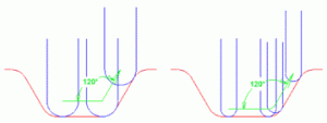
The graphic above shows the cutter machining into a sharp corner. The 120-degree change in vector direction in one block of code causes the machine to slow down dramatically. If the cutter can interpolate a more gradual change in direction, it will result in a noticeable reduction in cycle time.
The Haas high-speed machining option can process at a speed of up to 1000 blocks per second – that is, one block every one-thousandth of a second (1 millisecond). In order to maintain smooth, fluid motion, your program should not contain any block of code that takes less than 1 millisecond to execute.
For example, if your feedrate is 150 inches per minute, the commanded speed is 2.5 inches per second (150 / 60 = 2.5). If you divide 2.5 in/sec by 1000, you will find that, at 150 ipm, you travel 0.0025″ every millisecond.
You can determine the 3-dimensional distance traveled (D) in a linear block of code by using the following formula (d = distance moved in that axis):

For Example: When a rotary fits with alternative fixturing, it may fit in that particular Haas mill, but will require a sub-plate or alternate T-slot for proper positioning. We have labeled this particular rotary and mill combination with a yellow caution
You can design and build your own sub-plate using the dimensions of your Haas mill and the dimensions of the rotary you'd like to use on that mill. Product dimensions are available for every machine and rotary on this website.
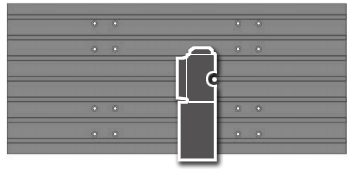
Single-Head Rotary Tables and Indexers are usually mounted to the right side of the table, with the rotary facing the centre of the machine. This is the basic setup we used to determine the fit of your rotary product.

Image shown for mounting example purposes only. Your actual rotary and mill appearance may differ.
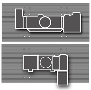
Trunnion Tables, T5Cs, and TRTs are usually mounted in the centre (or slightly off-centre) of the mill table. If you are using probing on the mill, be aware of the interference with larger tools, especially during tool changes.
NOTE: Trunnion units present interference issues with the swing of the unit relative to the machine column and spindle head.

Image shown for mounting example purposes only. Your actual rotary and mill appearance may differ.
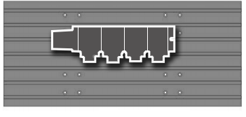
Multi-Head Rotary Tables and Indexers are usually mounted toward the back of the table, with the indexer heads or platter facing forward. To mount a multi-head rotary in a different orientation, you must use alternative fixturing.

Image shown for mounting example purposes only. Your actual rotary and mill appearance may differ.
Important Information:
4-axis machines cannot use dual-axis rotaries.
Some options may affect mounting (EC-1600 4th-Axis Table, Low-Profile Tables, Table Spacers, Column Risers, etc.
Tool Changers: SMTCs and umbrella tool changers both present interference issues, plan appropriately.

