Another Bite
We’re all familiar with dentists checking our jaw by pressing on the joint just ahead of our ears and saying: “Open. Close.” As we open and close our mouths, our jaw pivots at the temporomandibular joint (TMJ), allowing us to chew, talk, and even hold a soda straw in our teeth.
Unfortunately, TMJ problems often are more severe than just a “click” when you bite down. Many people experience pain and have difficulty performing simple jaw movements. Bone loss or loss of correct jaw position – due to rheumatoid arthritis, trauma, developmental abnormality, or tumor – can cause poor function, and lead to psychological issues due to deformity. For many of these cases, a TMJ implant can mean a dramatic improvement in the quality of life and mental health of the patient.
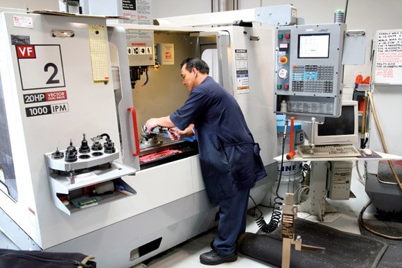
TMJ Concepts of Ventura, California, has pioneered a unique method for producing custom-fit TMJ implants using 3D rapid prototyping and CNC machine tools from Haas Automation (Oxnard, CA).
“We have four Haas CNC machines,” notes Dave Samson, president of TMJ Concepts, “an SL-10 lathe and three vertical machining centers – two VF-0s and a VF-2. The first VF-0 came from our previous business. It must be 20 years old, and still works great. We got the second VF-0 a couple of years later, and recently got the VF-2 and SL-10. We decided on Haas machines because they work great and don’t cost a lot.”
Samson emphasizes that the company’s implants are manufactured to strict FDA guidelines, using proven materials. “Prior to our company getting into this business,” he explains, “most products made for this purpose failed miserably. They’re now highly classified by the FDA – like heart valves and pacemakers – and require close scrutiny.”
In the ’70s and ’80s, some TMJ implants contained Teflon® and silicone in their construction – true wonder materials with hundreds of uses. However, those materials were ill suited for use in permanent TMJ prosthetics, as they eventually deteriorated into fine particles under the stress of chewing and biting. Some of these particles traveled throughout patients’ bodies via the lymph system, creating serious health problems. To overcome these issues, TMJ Concepts employs an ingenious mix of technology and materials.
The Fix Is In
Construction materials for TMJ implants must be strong, nontoxic and lacking any adverse impact on the patient’s tissues. TMJ Concepts uses materials that have been proven through decades of use in orthopedic shoulder, hip, and knee joint replacements. Properly machined titanium and titanium alloys make very strong implants that promote bonding with new bone growth.
Proper fit of the implant is just as important. A complex, high-stress joint like the TMJ requires a precision model for measurement comparison to ensure the implant fully contacts the bone surface for strength and proper function. Each patient undergoes a CT (CAT) scan to generate accurate images of the area of the jaw that will accept the implant. The scan data is used to create a 3D rapid-prototype copy of the patient’s bone structure – a resin skull – which becomes a template for the implant.
“Prior to any cutting, we want to see what we have to work with,” explains Samson. “With a 3D model, we can make custom-fit implants very accurately. And remember, each patient is different!”
The Implant
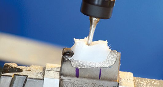
Generally, a TMJ implant consists of three parts. The ramus is a long arm element that fastens to the lower jaw. The condyle is a smooth, hard, metal ball about 3/16″ in diameter that attaches to the ramus to provide a pivot. The fossa is a grooved plastic block that attaches to the upper jaw, serving as a pivot surface for the condyle.
The ramus component of the implant requires particular attention. TMJ Concepts engineers scan the 3D resin model using a laser measuring instrument to record the surface curvatures of the jawbone where the implant will attach. They convert the measurement data into a CNC milling program to duplicate the surface (in reverse) on the ramus. Although the tolerances involved are not considered extremely close, compared to some other types of manufacturing, the complex geometry of the implant-to-bone surfaces lends itself well to CNC machining.
TMJ Concepts machines the ramus components from 6Al-4V ELI (extra-low interstitial) titanium alloy. “We square the titanium block with a 3-inch, 90-degree insert tool at slow speed – about 300 rpm and about 3 inches per minute,” says machinist Gilbert Naungayan. “Then we mill a trunnion onto the block for the condyle.”
The condyles are machined on the Haas SL-10 from cobalt-chromium-molybdenum bar stock. This material provides a smooth, low-friction pivot surface for the implant. The finished condyle is permanently pressed onto the trunnion of the titanium block, prior to cutting the ramus.
“The mill is touched-off on the condyle surface,” Naungayan continues, “and the VMC generates the bone-shaped surface of the ramus-component implant from the block. We cut with a finish speed of about 2350 rpm and a feed of 7.5 inches per minute, with flood coolant. We use a 0.007″ stepover with a 1/2″ ballnose endmill to get the right texture.” Finish texture is crucial to promoting bonding with new bone growth.
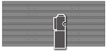
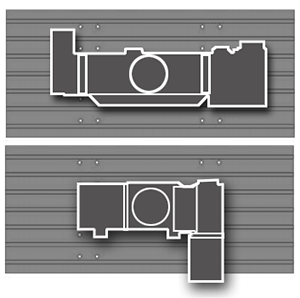
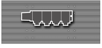
For the majority of their machining TMJ Concepts uses off-the-shelf tooling, but they’ve developed a custom-made setup to machine the reverse, smooth side of their implants. They mill the negative image of the ramus into a pair of aluminum blocks mounted together so the interface divides the pattern (similar to machining soft jaws for a vise). The blocks are put into a vise to form a clamp that holds the implant during machining.
After machining, the outside of the implant is polished, and then it is hand-fitted to the 3D model. This eliminates any high spots to provide good bone-to-implant contact – ensuring the implant will bond with the bone. Next, the hole positions are determined for the titanium-alloy screws that will fasten the implant to the bone. These are drilled and countersunk by hand.
The Fossa
The fossa assembly of the TMJ implant consists of a machined block of ultra-high-molecular-weight polyethylene bonded to a laminate of titanium plate and titanium mesh that is contoured to fit the patient’s upper jawbone.
To form the titanium mesh, TMJ concepts uses a laser 3D measuring instrument to scan the specific area of the resin skull model where the fossa will attach. This data is used to create CNC programs to mill both a positive and negative of the bone contour into blocks of wax. The blocks are then used as patterns to make investment-cast dies in the shape of the patient’s bone structure. “We sandwich a thin sheet of titanium between four sections of titanium mesh – two on top and two on the bottom,” Samson explains. “They’re pressed together between the dies in a vacuum furnace, so it fits the shape of the bone. That’s the base of the fossa. The mesh texture has tiny pockets that are perfect for biological activity,” he adds, “so new bone growth eventually bonds with the titanium mesh.”
The ultra-high-molecular-weight polyethylene block is bonded to the mesh using a precisely controlled combination of pressure, heat, and time. TMJ Concepts then mills the depression for the condyle into the block using one of the company’s Haas VMCs. After drilling holes for the titanium-alloy screws that will hold it in place, the fossa assembly is ready for cleaning, inspection, documentation, and, eventually, use.
“Everything has to be perfect,” says Samson. “We are certified to ISO and FDA standards, and the FDA is far more stringent than ISO. Due to the early failures with Teflon® and silicone by other companies, we have to track every patient, document everything, and account for every implant. We are meticulous, with very high quality standards.”
This is demanding, error-free manufacturing, requiring massive recordkeeping, very close inspection, and extremely high quality. But, for someone with bone loss, a birth deformity, or arthritis, a TMJ Concepts implant can literally give them a new life.


